Actuator modules
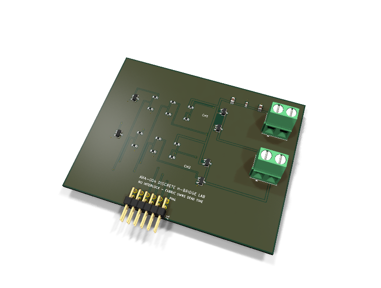
AXA-004 — Discrete H-bridge lab PMOD module
Catalog #4 in the AruviX actuator line, level L4. Four discrete FETs, no driver IC, no interlock: the FPGA drives all four gate signals and the fabric must guarantee dead time.
Circuit review & bench-test guide →
Components#
Every placed component, with the reason it is on the board. Extracted directly from the schematic, so this cannot drift from the design.
| Ref | Value | What it does on this board | Part number | Footprint |
|---|---|---|---|---|
C1 |
10uF 25V X5R | VM bulk reservoir for bridge switching current | GRM21BR61E106KA73LMurata |
C_0805_2012Metric |
C2 |
10uF 25V X5R | VM bulk reservoir for bridge switching current | GRM21BR61E106KA73LMurata |
C_0805_2012Metric |
C3 |
100nF 50V X7R | VM high-frequency decoupling at the bridge | GRM188R71H104KA93DMurata |
C_0603_1608Metric |
J1 |
PMOD PLUG 2x6 | PMOD peripheral plug (Digilent spec 1.2) | not selected generic |
PinHeader_2x06_P2.54mm_Horizontal |
J2 |
VM IN 5-12V | Motor supply input: 1 VM (5-12 V - AO3401A gate divider limit), 2 GND | not selected Phoenix Contact |
TerminalBlock_Phoenix_MKDS-1,5-2-5.08_1x02_P5.08mm_Horizontal |
J3 |
MOTOR | Bridge output: 1 OUT1, 2 OUT2 | not selected Phoenix Contact |
TerminalBlock_Phoenix_MKDS-1,5-2-5.08_1x02_P5.08mm_Horizontal |
Q1 |
AO3401A | Channel 1 high-side P-FET (-30 V -4 A) | AO3401AAlpha & Omega Datasheet ↗ |
SOT-23 |
Q2 |
AO3400A | Channel 1 low-side N-FET (30 V 5.7 A, logic level) | AO3400AAlpha & Omega Datasheet ↗ |
SOT-23 |
Q3 |
AO3400A | Channel 1 high-side gate level inverter (cancels to active-high) | AO3400AAlpha & Omega Datasheet ↗ |
SOT-23 |
Q4 |
AO3401A | Channel 2 high-side P-FET (-30 V -4 A) | AO3401AAlpha & Omega Datasheet ↗ |
SOT-23 |
Q5 |
AO3400A | Channel 2 low-side N-FET (30 V 5.7 A, logic level) | AO3400AAlpha & Omega Datasheet ↗ |
SOT-23 |
Q6 |
AO3400A | Channel 2 high-side gate level inverter (cancels to active-high) | AO3400AAlpha & Omega Datasheet ↗ |
SOT-23 |
R1 |
100R | HS1 inverter gate resistor | RC0603FR-07100RLYageo Datasheet ↗ |
R_0603_1608Metric |
R2 |
100R | LS1 gate resistor (damps gate ringing) | RC0603FR-07100RLYageo Datasheet ↗ |
R_0603_1608Metric |
R3 |
10k | HG1 pull-up to VM: high side OFF until the inverter conducts | RC0603FR-0710KLYageo Datasheet ↗ |
R_0603_1608Metric |
R4 |
10k | HG1 series half of the divider: Vsg = VM/2, gate rating safe to 12 V | RC0603FR-0710KLYageo Datasheet ↗ |
R_0603_1608Metric |
R5 |
10k | HS1 idle pull-down: unpowered host = bridge off | RC0603FR-0710KLYageo Datasheet ↗ |
R_0603_1608Metric |
R6 |
10k | LS1 idle pull-down: unpowered host = bridge off | RC0603FR-0710KLYageo Datasheet ↗ |
R_0603_1608Metric |
R7 |
100R | HS2 inverter gate resistor | RC0603FR-07100RLYageo Datasheet ↗ |
R_0603_1608Metric |
R8 |
100R | LS2 gate resistor (damps gate ringing) | RC0603FR-07100RLYageo Datasheet ↗ |
R_0603_1608Metric |
R9 |
10k | HG2 pull-up to VM: high side OFF until the inverter conducts | RC0603FR-0710KLYageo Datasheet ↗ |
R_0603_1608Metric |
R10 |
10k | HG2 series half of the divider: Vsg = VM/2, gate rating safe to 12 V | RC0603FR-0710KLYageo Datasheet ↗ |
R_0603_1608Metric |
R11 |
10k | HS2 idle pull-down: unpowered host = bridge off | RC0603FR-0710KLYageo Datasheet ↗ |
R_0603_1608Metric |
R12 |
10k | LS2 idle pull-down: unpowered host = bridge off | RC0603FR-0710KLYageo Datasheet ↗ |
R_0603_1608Metric |
Signals#
Net labels used in the schematic, which are also the names the HDL top level should use.
3V3 GND HG1 HG1_PD HG2 HG2_PD HS1 HS2 IG1 IG2 LG1 LG2 LS1 LS2 OUT1 OUT2 VMOT
Production status#
| Schematic ERC | 0 violations |
|---|---|
| PCB layout | complete |
| DRC | 0 violations |
| Fab package | exported (24 gerbers + drill + CPL + BOM) |
| Fabricated | no — design stage only |
Source: boards/actuator-modules/axa-004-hbridge-lab
Catalog #4 in the AruviX actuator line (../README.md), level L4. Four discrete FETs, no driver IC, no interlock: the FPGA drives all four gate signals and the fabric must guarantee dead time.
Status: schematic generated, ERC clean (0/0), netlist reviewed. PCB layout not started. Not released.
SHOOT-THROUGH IS PHYSICALLY POSSIBLE BY DESIGN. Driving HSx and LSx high together shorts VM to GND through both FETs of that leg. That is the point of the module:
deadtime_genplus a self-checking testbench must prove no overlap before a motor (or a fuse) is attached. There is no silicon safety net — exactly the honesty every integrated driver hides.
What it teaches#
Dead-time insertion the honest way: gate-drive levels, asymmetric propagation paths, body-diode conduction during dead time, and formal-ish testbench proof obligations. This is the L4 counterpart of AXA-001/002 — same H-bridge truth table, but every failure mode is yours.
Topology (think it through before powering)#
Per half-bridge (channel x = 1, 2):
- Low side: AO3400A N-FET, gate driven directly from PMOD LSx through 100 Ω. Logic-level FET, fully enhanced at 3.3 V. LSx = 1 → low side ON.
- High side: AO3401A P-FET, source at VM. A 3.3 V PMOD pin cannot swing a gate that lives near VM, so PMOD HSx (through 100 Ω) drives a small AO3400A level-inverter whose drain pulls the P-FET gate down through 10 kΩ, against a 10 kΩ pull-up to VM:
- Inverter OFF → gate = VM → V_SG = 0 → high side OFF.
- Inverter ON → the 10k/10k divider parks the gate at VM/2 → V_SG = VM/2 → high side ON. The inverter cancels the inversion: HSx = 1 → high side ON. All four PMOD signals are active-high.
- Gate-rating math (why VM is 5–12 V): V_SG = VM/2 is 6 V at VM = 12 V — inside the AO3401A ±12 V absolute maximum with 2× margin — and 2.5 V at VM = 5 V, the AO3401A's specified enhancement point (R_DS(on) rated at V_GS = −2.5 V). Below 5 V the high side barely turns on; above 12 V the divider erodes the gate-rating margin. VM range: 5–12 V.
- Timing asymmetry: the high-side path has an extra FET stage plus the 10k/10k RC into the P-FET gate, so it switches slower than the direct low-side path. Your dead time must cover the measured asymmetry — scope both gates; that measurement is part of the lab.
- Idle safety: 10 k pull-downs on all four PMOD nets — an unpowered or unconfigured host leaves all four FETs off.
- Flyback: FET body diodes only (documented per the line rule). During dead time the motor current freewheels through them — watch the diode drop appear on the scope, then shorten (not eliminate!) the dead time.
Design#
- 2× AO3401A (−30 V, −4 A) high side, 4× AO3400A (30 V, 5.7 A) low side + inverters, all SOT-23.
- Motor power VM on J2 screw terminal only, never through the PMOD; bulk 2× 10 µF 25 V 0805 + 100 nF 50 V at the bridge. Grounds join on the module.
- Bridge output OUT1/OUT2 → J3 screw terminal.
- All PMOD lines host-driven → no 100 Ω module-driven series rule; no fault or sense line exists (documented exception: the module is deliberately dumb — pair it with AXA-003 or a shunt lab for feedback).
| PMOD pin | 1 | 2 | 3 | 4 | 5 | 6 | 7 | 8 | 9 | 10 | 11 | 12 |
|---|---|---|---|---|---|---|---|---|---|---|---|---|
| Net | HS1 | LS1 | HS2 | LS2 | GND | 3V3 | NC | NC | NC | NC | GND | 3V3 |
Regenerate#
python3 generate_design.pyRemaining for release#
- [ ] PCB layout (20 × 40 mm actuator outline, tight bridge loop), DRC, fab outputs
- [ ]
hdl/:deadtime_gen+ bridge sequencer, self-checking no-overlap testbench (the release gate), ECP5 demo - [ ] BOM export and availability check, design-review checklist