Sensor modules
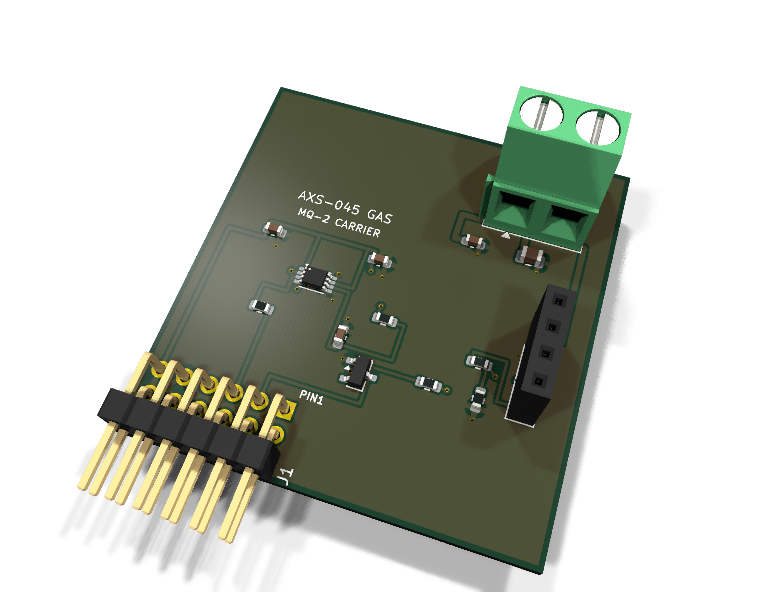
AXS-045 — MQ-series combustible-gas carrier PMOD module
Catalog #45 in the AruviX sensor line, level L3 (SPI ADC + 5 V domain handling).
Circuit review & bench-test guide →
Components#
Every placed component, with the reason it is on the board. Extracted directly from the schematic, so this cannot drift from the design.
| Ref | Value | What it does on this board | Part number | Footprint |
|---|---|---|---|---|
C1 |
100nF 16V X7R | ADS7042 AVDD/DVDD decoupling (place at the pins) | GRM188R71C104KA01DMurata |
C_0603_1608Metric |
C2 |
1uF 16V X5R | ADS7042 reference/bulk decoupling | GRM188R61C105KA93DMurata |
C_0603_1608Metric |
C3 |
10nF 50V C0G | RC filter / charge reservoir at the ADC input | GRM1885C1H103JA01DMurata |
C_0603_1608Metric |
C4 |
100nF 16V X7R | MQ socket supply decoupling | GRM188R71C104KA01DMurata |
C_0603_1608Metric |
C5 |
10uF 10V X5R | Heater bulk reservoir on the 5 V feed | GRM21BR61A106KE19LMurata |
C_0805_2012Metric |
D1 |
BAT54S | Series Schottky pair clamping GAS_DO between GND-0.3 V and 3V3+0.3 V | BAT54S,215Nexperia Datasheet ↗ |
SOT-23 |
J1 |
PMOD PLUG 2x6 | PMOD peripheral plug (Digilent spec 1.2) | not selected generic |
PinHeader_2x06_P2.54mm_Horizontal |
J2 |
MQ-2 BREAKOUT SOCKET | Socket for a common MQ-2 breakout: 1 VCC(5V), 2 GND, 3 DO, 4 AO | not selected generic |
PinSocket_1x04_P2.54mm_Vertical |
J3 |
EXT 5V IN | External 5 V for the MQ heater: 1 +5V, 2 GND (common with PMOD GND) | not selected Phoenix Contact |
TerminalBlock_Phoenix_MKDS-1,5-2-5.08_1x02_P5.08mm_Horizontal |
R1 |
10k | AO divider top: 10k/18k scales 5 V full-scale to 3.21 V | RC0603FR-0710KLYageo Datasheet ↗ |
R_0603_1608Metric |
R2 |
18k | AO divider bottom (5 V x 18/28 = 3.21 V < 3.3 V AVDD) | RC0603FR-0718KLYageo Datasheet ↗ |
R_0603_1608Metric |
R3 |
1k | RC anti-alias / charge-bucket source resistor into the SAR input | RC0603FR-071KLYageo Datasheet ↗ |
R_0603_1608Metric |
R4 |
10k | DO series limiter into the BAT54S clamp (5 V pull-up on cheap breakouts) | RC0603FR-0710KLYageo Datasheet ↗ |
R_0603_1608Metric |
R5 |
100R | Series protection on the ADC-driven data line | RC0603FR-07100RLYageo Datasheet ↗ |
R_0603_1608Metric |
U1 |
ADS7042 | 12-bit 1 MSPS SAR ADC, SPI, AVDD as reference | ADS7042IDCURTexas Instruments Datasheet ↗ |
VSSOP-8_2.3x2mm_P0.5mm |
Signals#
Net labels used in the schematic, which are also the names the HDL top level should use.
3V3 ADC_CS_N ADC_SDO EXT_5V GAS_AO GAS_DIV GAS_DO GAS_DO_RAW GAS_FILT GND MISO SCK
Production status#
| Schematic ERC | 0 violations |
|---|---|
| PCB layout | complete |
| DRC | 0 violations |
| Fab package | exported (24 gerbers + drill + CPL + BOM) |
| Fabricated | no — design stage only |
Source: boards/sensor-modules/axs-045-gas
Catalog #45 in the AruviX sensor line (../README.md), level L3 (SPI ADC + 5 V domain handling).
Status: schematic generated, ERC clean (0/0), netlist reviewed. PCB layout not started. Not released.
What it teaches#
Reading a genuinely awkward legacy sensor safely. The MQ-2 breakout is a 5 V part with a 0–5 V analog output and a comparator digital output that pulls to 5 V on cheap boards. The carrier demonstrates three standard defenses: an external supply domain, a resistive divider into an ADC, and a Schottky rail clamp — then digitizes with the same ADS7042 SPI pattern as AXS-040.
The 5 V requirement (read this first)#
The MQ heater requires external 5 V on the J3 screw terminal (~150 mA continuous — MQ sensors run hot by design and need minutes of warm-up before readings settle). J3 ground is common with the PMOD ground plane. Never feed 5 V into any PMOD pin.
Design#
- J2 = 1×4 pin socket for a common MQ-2 comparator breakout: 1 VCC (5 V), 2 GND, 3 DO, 4 AO. Breakout pin orders vary — verify against your board's silkscreen before fitting.
- AO path: 10 k / 18 k divider (5 V × 18/28 = 3.21 V < 3.3 V full scale), then RC 1 k + 10 nF into the ADS7042 AINP; AINM to GND. Multiply the ADC reading by 28/18 in fabric to recover the 0–5 V breakout level.
- DO path (danger handled): DO pulls up to VCC = 5 V on cheap breakouts. It passes a 10 k series resistor (R4) into a BAT54S series-Schottky pair (COM =
GAS_DO, A→GND, K→3V3), clamping the PMOD-side net to the 3.3 V rails. NetGAS_DOlands on PMOD pin 2. Do not bypass R4/D1. - 100 Ω series on the ADC-driven SDO line.
- ADC decoupling 100 nF + 1 µF (3V3); socket decoupling 100 nF + 10 µF (
EXT_5V). - PMOD Type 2 SPI for the ADC, DO as a GPIO input in the MOSI position.
| PMOD pin | 1 | 2 | 3 | 4 | 5 | 6 | 7 | 8 | 9 | 10 | 11 | 12 |
|---|---|---|---|---|---|---|---|---|---|---|---|---|
| Net | ~CS | GAS_DO | MISO | SCK | GND | 3V3 | NC | NC | NC | NC | GND | 3V3 |
Part substitutions vs. the module spec sketch: the spec explored a zener clamp (BZT52 3V6 / 3V3 + large series R) before settling on 10 k series + BAT54S to 3V3/GND, which clamps harder with less leakage spread; that is what is implemented. The KiCad Diode:BAT54S symbol's stock footprint is SOT-23 (BAT54S,215 is a SOT-23 part — a SOD-323 footprint would not fit this 3-pin device).
Regenerate#
python3 generate_design.pyRemaining for release#
- [ ] PCB layout (heater current path, clamp next to the PMOD edge), DRC, fab
- [ ] Pin the Phoenix terminal orderable part (MPN is
TBD:) - [ ] Verify MQ-2 breakout pin order against a purchased board
- [ ]
hdl/: SPI master + ADS7042 unpack, warm-up timer, threshold logic, testbench, ECP5 demo - [ ] BOM export and availability check, design-review checklist