I/O modules
AXO-015 — potentiometer + slider bank PMOD module
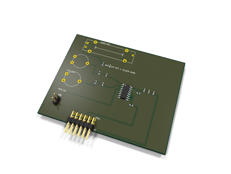
Catalog #15 in the AruviX output line, level L3. The "analog input fun" board: two rotary thumb pots and a real slide pot, all digitized by an MCP3008.
Circuit review & bench-test guide →
Components#
Every placed component, with the reason it is on the board. Extracted directly from the schematic, so this cannot drift from the design.
| Ref | Value | What it does on this board | Part number | Footprint |
|---|---|---|---|---|
C1 |
10nF 50V X7R | RC shunt on the pot 1 wiper: fc ~ 16 kHz | GRM188R71H103KA01DMurata |
C_0603_1608Metric |
C2 |
10nF 50V X7R | RC shunt on the pot 2 wiper: fc ~ 16 kHz | GRM188R71H103KA01DMurata |
C_0603_1608Metric |
C3 |
10nF 50V X7R | RC shunt on the slider wiper: fc ~ 16 kHz | GRM188R71H103KA01DMurata |
C_0603_1608Metric |
C4 |
100nF 16V X7R | VDD decoupling | GRM188R71C104KA01DMurata |
C_0603_1608Metric |
C5 |
100nF 16V X7R | VREF decoupling | GRM188R71C104KA01DMurata |
C_0603_1608Metric |
C6 |
1uF 10V X7R | Supply bulk decoupling | GRM188R71A105KA61DMurata |
C_0603_1608Metric |
J1 |
PMOD PLUG 2x6 | PMOD peripheral plug (Digilent spec 1.2) | not selected generic |
PinHeader_2x06_P2.54mm_Horizontal |
J3 |
CH3 SPARE | Spare analog input: CH3 + GND return | not selected generic |
PinHeader_1x02_P2.54mm_Vertical |
R1 |
1k | RC series element on the pot 1 wiper | RC0603FR-071KLYageo Datasheet ↗ |
R_0603_1608Metric |
R2 |
1k | RC series element on the pot 2 wiper | RC0603FR-071KLYageo Datasheet ↗ |
R_0603_1608Metric |
R3 |
1k | RC series element on the slider wiper | RC0603FR-071KLYageo Datasheet ↗ |
R_0603_1608Metric |
R4 |
10k | ~CS idle pull-up so an unconfigured host cannot start a conversion | RC0603FR-0710KLYageo Datasheet ↗ |
R_0603_1608Metric |
R5 |
100R | Series protection on the ADC-driven DOUT line | RC0603FR-07100RLYageo Datasheet ↗ |
R_0603_1608Metric |
RV1 |
10k ROTARY | Rotary thumb pot 1: full-rail, wiper to CH0 | PT10MV10-103A2020-SPiher Datasheet ↗ |
Potentiometer_Piher_PT-10-V10_Vertical |
RV2 |
10k ROTARY | Rotary thumb pot 2: full-rail, wiper to CH1 | PT10MV10-103A2020-SPiher Datasheet ↗ |
Potentiometer_Piher_PT-10-V10_Vertical |
RV3 |
10k SLIDE | Slide pot (20 mm travel): full-rail, wiper to CH2 | PTA2043-2015CPB103Bourns Datasheet ↗ |
Potentiometer_Bourns_PTA2043_Single_Slide |
U1 |
MCP3008 | 8-channel 10-bit SAR ADC, SPI, 200 ksps | MCP3008-I/SLMicrochip Datasheet ↗ |
SOIC-16_3.9x9.9mm_P1.27mm |
Signals#
Net labels used in the schematic, which are also the names the HDL top level should use.
3V3 ADC_DOUT CH3 CS_N GND MISO MOSI POT1 POT1_W POT2 POT2_W SCK SLIDE SLIDE_W
Production status#
| Schematic ERC | 0 violations |
|---|---|
| PCB layout | complete |
| DRC | 0 violations |
| Fab package | exported (24 gerbers + drill + CPL + BOM) |
| Fabricated | no — design stage only |
Source: boards/io-modules/axo-015-pots
Catalog #15 in the AruviX output line (../README.md), level L3. The "analog input fun" board: two rotary thumb pots and a real slide pot, all digitized by an MCP3008.
Status: schematic generated, ERC clean (0/0), netlist reviewed. PCB layout not started. Not released.
What it teaches#
Three continuously-variable human inputs: mixer faders, synth knobs (with the DDS module axo-010), RGB color mixing on the LED bar, PID setpoint twiddling. Same SPI ADC protocol as axs-031, so the HDL carries over.
Part picks (verified against stock KiCad 9 libraries)#
- Rotary (RV1, RV2): Piher PT-10 vertical — footprint
Potentiometer_THT:Potentiometer_Piher_PT-10-V10_Vertical(stock, pads 1/2/3), MPN PT10MV10-103A2020-S (10 k linear). Chosen over the catalog's TC33X suggestion: the TC33X is a screwdriver trimmer, not finger-adjustable; the PT-10 vertical takes a thumbwheel/shaft. - Slide (RV3): a stock slide-pot footprint EXISTS —
Potentiometer_THT:Potentiometer_Bourns_PTA2043_Single_Slide(pads 1/2/3 + MP), so the catalog's "substitute a third rotary" fallback is not needed. MPN PTA2043-2015CPB103 (10 k linear, 20 mm travel). SymbolDevice:R_Potentiometer_MountingPincarries the MP pad, tied to GND. - ADC:
Analog_ADC:MCP3008(8-ch 10-bit SPI, proven in axs-031), MCP3008-I/SL, SOIC-16.
Channel plan#
| MCP3008 | CH0 | CH1 | CH2 | CH3 | CH4–CH7 |
|---|---|---|---|---|---|
| Source | pot 1 | pot 2 | slider | spare on J3 (1×02, with GND) | grounded |
Each wiper passes 1 k + 10 nF (fc ≈ 16 kHz) before its channel — scratch filter plus SAR charge reservoir. CH4–CH7 are grounded so no SAR input ever floats. VREF = VDD = 3V3: knob position maps linearly to the 10-bit scale.
Support parts per platform convention: 10 k ~CS idle pull-up, 100 Ω on the ADC-driven DOUT→MISO line, 100 nF on VDD and VREF + 1 µF bulk.
PMOD pin map (Type 2 SPI)#
| PMOD pin | 1 | 2 | 3 | 4 | 5 | 6 | 7 | 8 | 9 | 10 | 11 | 12 |
|---|---|---|---|---|---|---|---|---|---|---|---|---|
| Net | CS_N | MOSI | MISO | SCK | GND | 3V3 | NC | NC | NC | NC | GND | 3V3 |
Regenerate#
python3 generate_design.pyRemaining for release#
- [ ] PCB layout (pots on the outer edge for finger clearance; slider travel axis along the board), DRC, fab outputs
- [ ]
hdl/: reuse the axs-031 MCP3008 read core; 3-channel scan demo - [ ] BOM export and availability check, design-review checklist