Sensor modules
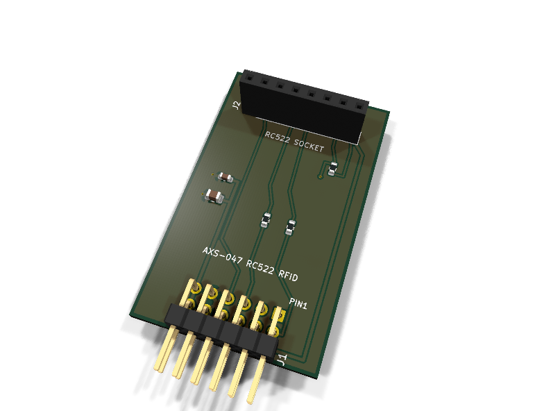
AXS-047 — RC522 RFID carrier PMOD module
Catalog #47 in the AruviX sensor line, level L3 (SPI).
Circuit review & bench-test guide →
Components#
Every placed component, with the reason it is on the board. Extracted directly from the schematic, so this cannot drift from the design.
| Ref | Value | What it does on this board | Part number | Footprint |
|---|---|---|---|---|
C1 |
100nF 16V X7R | Socket decoupling | GRM188R71C104KA01DMurata |
C_0603_1608Metric |
C2 |
10uF 10V X5R | RF transmit-burst bulk reservoir at the socket | GRM21BR61A106KE19LMurata |
C_0805_2012Metric |
J1 |
PMOD PLUG 2x6 | PMOD peripheral plug (Digilent spec 1.2) | not selected generic |
PinHeader_2x06_P2.54mm_Horizontal |
J2 |
RC522 SOCKET | Socket for the common RC522 breakout: 1 SDA/SS, 2 SCK, 3 MOSI, 4 MISO, 5 IRQ, 6 GND, 7 RST, 8 3.3V | not selected generic |
PinSocket_1x08_P2.54mm_Vertical |
R1 |
100R | Series protection on the module-driven MISO line | RC0603FR-07100RLYageo Datasheet ↗ |
R_0603_1608Metric |
R2 |
100R | Series protection on the module-driven IRQ line | RC0603FR-07100RLYageo Datasheet ↗ |
R_0603_1608Metric |
R3 |
10k | RST_N pull-up: reader out of reset until the host drives it low | RC0603FR-0710KLYageo Datasheet ↗ |
R_0603_1608Metric |
Signals#
Net labels used in the schematic, which are also the names the HDL top level should use.
3V3 CS_N GND MISO MOSI RC522_IRQ RC522_MISO RFID_IRQ RST_N SCK
Production status#
| Schematic ERC | 0 violations |
|---|---|
| PCB layout | complete |
| DRC | 0 violations |
| Fab package | exported (24 gerbers + drill + CPL + BOM) |
| Fabricated | no — design stage only |
Source: boards/sensor-modules/axs-047-rfid
Catalog #47 in the AruviX sensor line (../README.md), level L3 (SPI).
Status: schematic generated, ERC clean (0/0), netlist reviewed. PCB layout not started. Not released.
What it teaches#
A real SPI register map. The MFRC522 is not a "clock out a frame" device: it has FIFOs, interrupt registers, a CRC coprocessor, and timeouts. On top of that sits the ISO14443A protocol lesson — REQA, anticollision, SELECT — to read MIFARE card UIDs. The IRQ line (PMOD pin 7) motivates interrupt-driven design over polling.
Design#
This is a carrier for the ubiquitous RC522 blue board (3.3 V only) on a 1×8 socket, J2, in the common blue-board order:
1 SDA(SS), 2 SCK, 3 MOSI, 4 MISO, 5 IRQ, 6 GND, 7 RST, 8 3.3V
Clone boards occasionally differ — verify your breakout's silkscreen against the J2 order before fitting. (The blue board straps the MFRC522 into SPI mode; the "SDA" pin is the SPI ~SS.)
- 100 Ω series on the module-driven MISO and IRQ lines.
- RST_N pulled up to 3V3 with 10 k on-module (reader out of reset by default); host-driven from PMOD pin 8.
- ~CS, MOSI, SCK host-driven, wired directly.
- 100 nF + 10 µF at the socket (RF transmit bursts).
- PMOD Type 2A (expanded SPI): IRQ on pin 7, reset on pin 8.
| PMOD pin | 1 | 2 | 3 | 4 | 5 | 6 | 7 | 8 | 9 | 10 | 11 | 12 |
|---|---|---|---|---|---|---|---|---|---|---|---|---|
| Net | CS_N | MOSI | MISO | SCK | GND | 3V3 | RFID_IRQ | RST_N | NC | NC | GND | 3V3 |
Regenerate#
python3 generate_design.pyRemaining for release#
- [ ] PCB layout (keep carrier copper clear of the breakout's antenna area), DRC, fab
- [ ] Verify RC522 breakout pin order against a purchased board
- [ ]
hdl/: SPI master, MFRC522 register layer, ISO14443A UID read FSM, testbench, ECP5 demo - [ ] BOM export and availability check, design-review checklist