Actuator modules
AXA-011 — RS-485 node PMOD module
Catalog #11 in the AruviX actuator line, level L3. MAX3485 3.3 V half-duplex RS-485 transceiver — the pragmatic multi-drop bus for robots that just need to work.
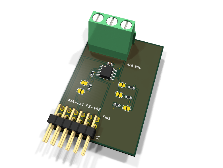
Circuit review & bench-test guide →
Components#
Every placed component, with the reason it is on the board. Extracted directly from the schematic, so this cannot drift from the design.
| Ref | Value | What it does on this board | Part number | Footprint |
|---|---|---|---|---|
C1 |
100nF 16V X7R | VCC decoupling | GRM188R71C104KA01DMurata |
C_0603_1608Metric |
J1 |
PMOD PLUG 2x6 | PMOD peripheral plug (Digilent spec 1.2) | not selected generic |
PinHeader_2x06_P2.54mm_Horizontal |
J2 |
RS-485 BUS (A/B/GND) | RS-485 bus: 1 A (non-inverting), 2 B (inverting), 3 GND reference | not selected Phoenix Contact |
TerminalBlock_Phoenix_MKDS-1,5-3-5.08_1x03_P5.08mm_Horizontal |
JP1 |
RE=DE | Bridged default: DE drives ~RE (transmit mutes the receiver) | — | SolderJumper-2_P1.3mm_Bridged_RoundedPad1.0x1.5mm |
JP2 |
RE=PMOD4 | Open default: bridge (and cut JP1) to control ~RE from PMOD pin 4 | — | SolderJumper-2_P1.3mm_Open_RoundedPad1.0x1.5mm |
JP3 |
TERM 120R | Open default: bridge at the two physical bus ends only | — | SolderJumper-2_P1.3mm_Open_RoundedPad1.0x1.5mm |
JP4 |
BIAS A | Open default: bridge (with JP5) at exactly one node for failsafe bias | — | SolderJumper-2_P1.3mm_Open_RoundedPad1.0x1.5mm |
JP5 |
BIAS B | Open default: bridge (with JP4) at exactly one node for failsafe bias | — | SolderJumper-2_P1.3mm_Open_RoundedPad1.0x1.5mm |
R1 |
100R | Series protection on the transceiver-driven RXD line | RC0603FR-07100RLYageo Datasheet ↗ |
R_0603_1608Metric |
R2 |
10k | DE pull-down: node idles as receiver until the host drives DE high | RC0603FR-0710KLYageo Datasheet ↗ |
R_0603_1608Metric |
R3 |
120R 1% | Bus termination (behind JP3) | RC0603FR-07120RLYageo Datasheet ↗ |
R_0603_1608Metric |
R4 |
390R 1% | Failsafe bias: A to 3V3 (behind JP4). 390R holds A-B at 236 mV with both bus ends terminated (60R); 560R gave only 168 mV, under the 200 mV spec | RC0603FR-07390RLYageo Datasheet ↗ |
R_0603_1608Metric |
R5 |
390R 1% | Failsafe bias: B to GND (behind JP5). Matched to R4 so the bias divider is symmetric about the bus common mode | RC0603FR-07390RLYageo Datasheet ↗ |
R_0603_1608Metric |
U1 |
MAX3485 | 3.3 V half-duplex RS-485/RS-422 transceiver, 10 Mbps | MAX3485ESA+Analog Devices Datasheet ↗ |
SOIC-8_3.9x4.9mm_P1.27mm |
Signals#
Net labels used in the schematic, which are also the names the HDL top level should use.
3V3 A A_BIAS B B_BIAS DE GND RE_HOST RE_N RS_RO RXD TERM_A TXD
Production status#
| Schematic ERC | 0 violations |
|---|---|
| PCB layout | complete |
| DRC | 0 violations |
| Fab package | exported (24 gerbers + drill + CPL + BOM) |
| Fabricated | no — design stage only |
Source: boards/actuator-modules/axa-011-rs485
Catalog #11 in the AruviX actuator line (../README.md), level L3. MAX3485 3.3 V half-duplex RS-485 transceiver — the pragmatic multi-drop bus for robots that just need to work.
Status: schematic generated, ERC clean (0/0), netlist reviewed. PCB layout not started. Not released.
What it teaches#
UART framing in fabric plus the half-duplex skill: driver-enable turnaround. The fabric asserts DE for exactly the frame it transmits, releases the bus before the reply, and the whole class shares one cable pair. Scope the turnaround dead time; count bit times.
Design#
- MAX3485ESA+ (Analog Devices/Maxim, SOIC-8). 3.3 V supply from the PMOD — this module has no external power terminal (a transceiver is a logic-class load, well under the PMOD's ~100 mA budget).
- Bus terminal J2: 1x03 screw terminal A / B / GND (carry the GND reference in the cable on long runs).
- Receiver-enable scheme: ~RE is jumpered.
- JP1 (bridged, default): DE drives ~RE — transmitting mutes the receiver, no local echo. One host pin (PMOD 1) does the turnaround.
- JP2 (open): cut JP1 and bridge JP2 to drive ~RE from PMOD 4 independently (leave the receiver on while transmitting for a local-echo self-test, or force-listen).
- DE has a 10 k pull-down: an unconfigured host means the node listens.
- RO (transceiver-driven) passes R1 100 Ω to PMOD 3 (line rule).
- Termination JP3 (open, default): 120 Ω across A/B. Bridge at the two physical ends of the bus only.
- Failsafe bias JP4/JP5 (open, default): 560 Ω A→3V3 and B→GND. Bridge both at exactly one node per bus. The MAX3485 receiver failsafe covers open inputs only — an idle terminated bus floats to 0 V differential and chatters without this bias (that is the failsafe lesson).
- PMOD map uses spec-1.2.0 Type 3 UART positions: pin 2 TXD, pin 3 RXD, with DE in the pin-1 CTS slot and the ~RE override in the pin-4 RTS slot.
| PMOD pin | 1 | 2 | 3 | 4 | 5 | 6 | 7 | 8 | 9 | 10 | 11 | 12 |
|---|---|---|---|---|---|---|---|---|---|---|---|---|
| Net | DE | TXD | RXD | ~RE override | GND | 3V3 | NC | NC | NC | NC | GND | 3V3 |
Note: generate_design.py locally patches the shared emitter's derived- symbol flattening (empty child Footprint must inherit the parent's, matching KiCad's Flatten() rule) so the embedded MAX3485 matches the library copy.
Regenerate#
python3 generate_design.pyRemaining for release#
- [ ] PCB layout (20 × 40 mm actuator outline), DRC, fab outputs
- [ ]
hdl/: UART + DE turnaround controller, self-checking testbench, two-node ECP5 demo - [ ] BOM export and availability check, design-review checklist