Sensor modules
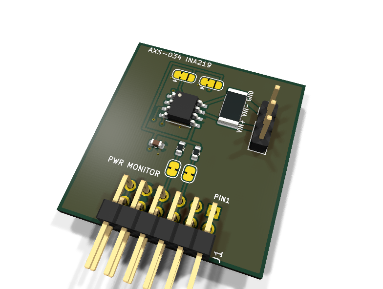
AXS-034 — INA219 current/power monitor PMOD module
Catalog #34, level L3 (I2C, fixed-point calibration).
Circuit review & bench-test guide →
Components#
Every placed component, with the reason it is on the board. Extracted directly from the schematic, so this cannot drift from the design.
| Ref | Value | What it does on this board | Part number | Footprint |
|---|---|---|---|---|
C1 |
100nF 16V X7R | Supply decoupling | GRM188R71C104KA01DMurata |
C_0603_1608Metric |
J1 |
PMOD PLUG 2x6 | PMOD peripheral plug (Digilent spec 1.2) | not selected generic |
PinHeader_2x06_P2.54mm_Horizontal |
J2 |
LOAD PATH | 1 supply-in, 2 load-out (through shunt), 3 GND reference | — | PinHeader_1x03_P2.54mm_Vertical |
JP1 |
SDA PULL-UP | Cut to remove the SDA pull-up when chaining modules | — | SolderJumper-2_P1.3mm_Bridged_RoundedPad1.0x1.5mm |
JP2 |
SCL PULL-UP | Cut to remove the SCL pull-up when chaining modules | — | SolderJumper-2_P1.3mm_Bridged_RoundedPad1.0x1.5mm |
JP3 |
A0 | A0 select: 1-2 GND (default), 2-3 VDD | — | SolderJumper-3_P1.3mm_Bridged12_RoundedPad1.0x1.5mm |
JP4 |
A1 | A1 select: 1-2 GND (default), 2-3 VDD | — | SolderJumper-3_P1.3mm_Bridged12_RoundedPad1.0x1.5mm |
R1 |
4.7k | I2C SDA pull-up | RC0603FR-074K7LYageo Datasheet ↗ |
R_0603_1608Metric |
R2 |
4.7k | I2C SCL pull-up | RC0603FR-074K7LYageo Datasheet ↗ |
R_0603_1608Metric |
R5 |
0.1R 1% 2W | Current shunt (kelvin-route the sense traces at layout) | CRA2512-FZ-R100ELFBourns |
R_2512_6332Metric |
U1 |
INA219 | High-side current shunt and power monitor, 26 V bus | INA219AIDRTexas Instruments Datasheet ↗ |
SOIC-8_3.9x4.9mm_P1.27mm |
Signals#
Net labels used in the schematic, which are also the names the HDL top level should use.
3V3 A0 A1 GND SCL SCL_PU SDA SDA_PU VIN_M VIN_P
Production status#
| Schematic ERC | 0 violations |
|---|---|
| PCB layout | complete |
| DRC | 0 violations |
| Fab package | exported (24 gerbers + drill + CPL + BOM) |
| Fabricated | no — design stage only |
Source: boards/sensor-modules/axs-034-ina219
Catalog #34 (../README.md), level L3 (I2C, fixed-point calibration).
Status: schematic generated, ERC clean (0/0), netlist reviewed. PCB layout not started. Not released.
What it teaches#
High-side current sensing and the INA219 calibration-register dance (current_LSB selection, calibration value, overflow handling) — fixed-point design with a purpose. Measure the AruviX board's own rails.
Design#
- TI INA219A (SOIC-8) + 0.1 Ω 1 % 2 W shunt (2512): 3.2 A full scale at the ±320 mV PGA setting.
- Load path on J2: 1 = supply in, 2 = load out (through the shunt), 3 = GND reference. Bus rail up to 26 V; grounds must be common.
- Address 0x40–0x45 via JP3 (A0) and JP4 (A1), both default GND.
- Layout note: kelvin-route IN+/IN− to the shunt pads.
Regenerate / remaining#
python3 generate_design.py — then PCB layout (kelvin sense), HDL, BOM check, checklist.