I/O modules
AXO-014 — IR remote link PMOD module
Catalog #14 in the AruviX output line, level L3. Both halves of an IR remote link on one module: 38 kHz demodulating receiver (RX) and 940 nm emitter (TX).
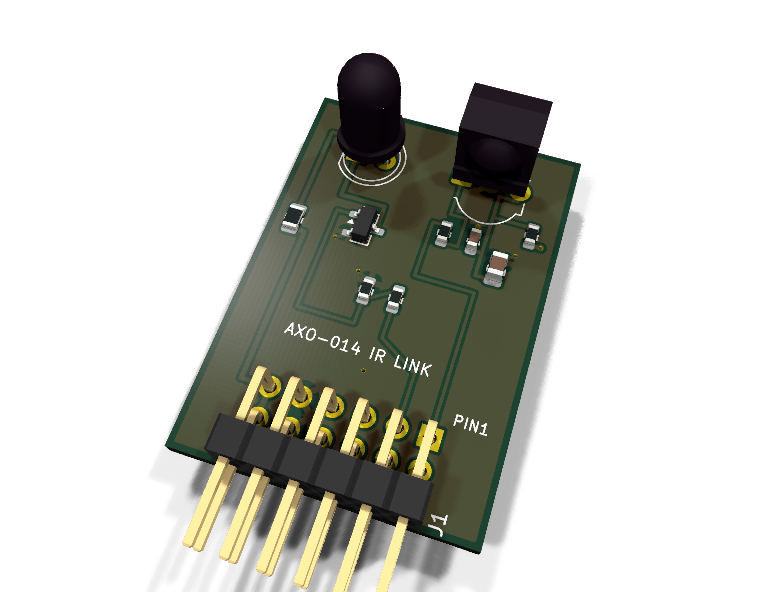
Circuit review & bench-test guide →
Components#
Every placed component, with the reason it is on the board. Extracted directly from the schematic, so this cannot drift from the design.
| Ref | Value | What it does on this board | Part number | Footprint |
|---|---|---|---|---|
C1 |
10uF 10V X5R | Receiver supply RC filter bulk (datasheet recommends >= 4.7uF) | GRM21BR61A106KE19LMurata |
C_0805_2012Metric |
C2 |
100nF 16V X7R | Receiver Vs pin decoupling | GRM188R71C104KA01DMurata |
C_0603_1608Metric |
D1 |
TSAL6400 | 940 nm 5 mm IR emitter, 100 mA continuous / 200 mA pulse | TSAL6400Vishay Datasheet ↗ |
LED_D5.0mm_IRBlack |
J1 |
PMOD PLUG 2x6 | PMOD peripheral plug (Digilent spec 1.2) | not selected generic |
PinHeader_2x06_P2.54mm_Horizontal |
Q1 |
AO3400A | Emitter low-side switch (N-channel, 5.7 A, ~30 mOhm at 2.5 Vgs) | AO3400AAlpha & Omega Semiconductor Datasheet ↗ |
SOT-23 |
R1 |
47R | Receiver supply RC filter series element (datasheet app circuit) | RC0603FR-0747RLYageo Datasheet ↗ |
R_0603_1608Metric |
R2 |
100R | Series protection on the receiver-driven (push-pull) output line | RC0603FR-07100RLYageo Datasheet ↗ |
R_0603_1608Metric |
R3 |
33R | Emitter ballast: (3.3 - 1.35 - Rds*I)/33 ~ 57 mA peak; 0805 for I^2R | RC0805FR-0733RLYageo Datasheet ↗ |
R_0805_2012Metric |
R4 |
1k | Gate series resistor from PMOD 2 | RC0603FR-071KLYageo Datasheet ↗ |
R_0603_1608Metric |
R5 |
10k | Gate pull-down: emitter OFF while the host pin is unconfigured | RC0603FR-0710KLYageo Datasheet ↗ |
R_0603_1608Metric |
U1 |
TSDP34138 | IR receiver for data links, 38 kHz carrier, 940 nm, push-pull output | TSDP34138Vishay Datasheet ↗ |
Vishay_MOLD-3Pin |
Signals#
Net labels used in the schematic, which are also the names the HDL top level should use.
3V3 GND IR_OUT IR_RX IR_TX IR_TX_G IR_VS LED_A LED_K
Production status#
| Schematic ERC | 0 violations |
|---|---|
| PCB layout | complete |
| DRC | 0 violations |
| Fab package | exported (24 gerbers + drill + CPL + BOM) |
| Fabricated | no — design stage only |
Source: boards/io-modules/axo-014-ir
Catalog #14 in the AruviX output line (../README.md), level L3. Both halves of an IR remote link on one module: 38 kHz demodulating receiver (RX) and 940 nm emitter (TX).
Status: schematic generated, ERC clean (0/0), netlist reviewed. PCB layout not started. Not released.
What it teaches — the NEC protocol, both directions#
- Decode (
nec_ir_rxcore): the TSDP34138 strips the 38 kHz carrier and hands the FPGA a clean demodulated bitstream (idle high, active low). NEC framing: 9 ms AGC burst + 4.5 ms space, then 32 bits of address/~address/command/~command, each bit a 562.5 µs burst followed by a 562.5 µs (0) or 1.6875 ms (1) space. Point any TV remote at it. - Encode (
nec_ir_txcore): the FPGA generates its own 38 kHz carrier, gates it with NEC bursts, and drives the TSAL6400 — remote-control the actuator-line robot (IR-remote robot project in../README.md).
Receiver design (verified against stock assets)#
Interface_Optical:TSDP341xx(stock symbol), footprintOptoDevice:Vishay_MOLD-3Pin(the symbol's own default — verified present), MPN TSDP34138 (38 kHz, 940 nm, data-link grade).- Output type check (per the catalog's open question): the stock symbol types OUT as
output(push-pull), matching the TSDP341xx datasheet's push-pull driver stage — unlike TSOP parts whose active-low out relies on an internal ~30 k pull-up. No external pull-up fitted; OUT passes the standard 100 Ω series to PMOD 1. - Supply RC: 47 Ω + 10 µF (+100 nF at the pin). The TSDP341xx datasheet application circuit recommends an R-C in Vs (47 Ω with ≥4.7 µF) to suppress supply disturbance; 10 µF is fitted as a superset. Noted in the generator header; re-verify against the datasheet at design review. The filtered
IR_VSnet carries its own PWR_FLAG (axs-034 pattern).
Emitter design and the current math#
3V3 → 33 Ω (0805) → TSAL6400 → AO3400A (low-side) → GND, gate 1 k from PMOD 2 with a 10 k pull-down (emitter off while the host is unconfigured).
- Peak current: I = (3.3 − V_F − I·Rds(on)) / 33 Ω with V_F(TSAL6400) ≈ 1.35 V and Rds(on)(AO3400A @ 2.5 Vgs) ≈ 30 mΩ → ≈ 57 mA peak (the catalog's "~40 mA" estimate was conservative; the real value is stated here per the compute-and-state requirement).
- Duty: 57 mA < the TSAL6400's 100 mA continuous rating, so no duty cycle can damage it. Normal NEC traffic (38 kHz at 50 % carrier duty, gated by bursts) averages < 20 mA. Drive IR_TX with the carrier, not DC — a stuck-high pin is safe but wastes ~190 mW and floods the room.
- The 33 Ω ballast is an 0805 (RC0805FR-0733RL): I²R ≈ 107 mW peak exceeds an 0603's 100 mW DC rating.
- Emitter footprint: stock
LED_THT:LED_D5.0mm_IRBlack, MPN Vishay TSAL6400 (5 mm, 940 nm).
PMOD pin map (Type 1 GPIO)#
| PMOD pin | 1 | 2 | 3 | 4 | 5 | 6 | 7 | 8 | 9 | 10 | 11 | 12 |
|---|---|---|---|---|---|---|---|---|---|---|---|---|
| Net | IR_RX | IR_TX | NC | NC | GND | 3V3 | NC | NC | NC | NC | GND | 3V3 |
Regenerate#
python3 generate_design.pyRemaining for release#
- [ ] PCB layout (RX shaded from the TX LED's side lobe; both at the board edge), DRC, fab outputs
- [ ]
hdl/:nec_ir_rx/nec_ir_txcores + loopback testbench - [ ] Datasheet re-verify: TSDP341xx supply-RC values and output stage
- [ ] BOM export and availability check, design-review checklist