Actuator modules
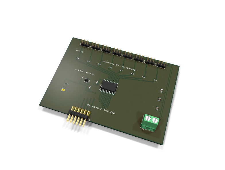
AXA-005 — 8-channel RC servo bank PMOD module
Catalog #5 in the AruviX actuator line, level L2. A 74HCT541 octal buffer, powered from an on-board 5 V LDO, fans eight host PWM lines out to eight standard SIG/V+/GND servo headers.
Circuit review & bench-test guide →
Components#
Every placed component, with the reason it is on the board. Extracted directly from the schematic, so this cannot drift from the design.
| Ref | Value | What it does on this board | Part number | Footprint |
|---|---|---|---|---|
C1 |
100nF 16V X7R | 74HCT541 supply decoupling | GRM188R71C104KA01DMurata |
C_0603_1608Metric |
C2 |
10uF 25V X5R | VSERVO bulk reservoir for servo stall/step transients | GRM21BR61E106KA73LMurata |
C_0805_2012Metric |
C3 |
10uF 25V X5R | VSERVO bulk reservoir for servo stall/step transients | GRM21BR61E106KA73LMurata |
C_0805_2012Metric |
C4 |
10uF 25V X5R | VSERVO bulk reservoir for servo stall/step transients | GRM21BR61E106KA73LMurata |
C_0805_2012Metric |
C5 |
1uF 25V X7R | AP2204K input capacitor (datasheet minimum 1 uF ceramic) | GRM188R71E105KA12DMurata |
C_0603_1608Metric |
C6 |
1uF 25V X7R | AP2204K output capacitor (datasheet minimum 1 uF ceramic for stability) | GRM188R71E105KA12DMurata |
C_0603_1608Metric |
J1 |
PMOD PLUG 2x6 | PMOD peripheral plug (Digilent spec 1.2) | not selected generic |
PinHeader_2x06_P2.54mm_Horizontal |
J3 |
VSERVO IN 5-6V | Servo supply input: 1 VSERVO (5-6 V), 2 GND (joins PMOD GND here) | not selected Phoenix Contact |
TerminalBlock_Phoenix_MKDS-1,5-2-5.08_1x02_P5.08mm_Horizontal |
J4 |
SERVO 1 | Servo channel 1: 1 SIG, 2 VSERVO, 3 GND (standard servo order) | not selected generic |
PinHeader_1x03_P2.54mm_Vertical |
J5 |
SERVO 2 | Servo channel 2: 1 SIG, 2 VSERVO, 3 GND (standard servo order) | not selected generic |
PinHeader_1x03_P2.54mm_Vertical |
J6 |
SERVO 3 | Servo channel 3: 1 SIG, 2 VSERVO, 3 GND (standard servo order) | not selected generic |
PinHeader_1x03_P2.54mm_Vertical |
J7 |
SERVO 4 | Servo channel 4: 1 SIG, 2 VSERVO, 3 GND (standard servo order) | not selected generic |
PinHeader_1x03_P2.54mm_Vertical |
J8 |
SERVO 5 | Servo channel 5: 1 SIG, 2 VSERVO, 3 GND (standard servo order) | not selected generic |
PinHeader_1x03_P2.54mm_Vertical |
J9 |
SERVO 6 | Servo channel 6: 1 SIG, 2 VSERVO, 3 GND (standard servo order) | not selected generic |
PinHeader_1x03_P2.54mm_Vertical |
J10 |
SERVO 7 | Servo channel 7: 1 SIG, 2 VSERVO, 3 GND (standard servo order) | not selected generic |
PinHeader_1x03_P2.54mm_Vertical |
J11 |
SERVO 8 | Servo channel 8: 1 SIG, 2 VSERVO, 3 GND (standard servo order) | not selected generic |
PinHeader_1x03_P2.54mm_Vertical |
JP1 |
OUTPUT ENABLE | Bridged: ~OE1/~OE2 grounded, outputs enabled. Cut: R17 pulls enables high, outputs hi-Z | — | SolderJumper-2_P1.3mm_Bridged_RoundedPad1.0x1.5mm |
R1 |
100R | Series damping/protection on servo channel 1 signal | RC0603FR-07100RLYageo Datasheet ↗ |
R_0603_1608Metric |
R2 |
100R | Series damping/protection on servo channel 2 signal | RC0603FR-07100RLYageo Datasheet ↗ |
R_0603_1608Metric |
R3 |
100R | Series damping/protection on servo channel 3 signal | RC0603FR-07100RLYageo Datasheet ↗ |
R_0603_1608Metric |
R4 |
100R | Series damping/protection on servo channel 4 signal | RC0603FR-07100RLYageo Datasheet ↗ |
R_0603_1608Metric |
R5 |
100R | Series damping/protection on servo channel 5 signal | RC0603FR-07100RLYageo Datasheet ↗ |
R_0603_1608Metric |
R6 |
100R | Series damping/protection on servo channel 6 signal | RC0603FR-07100RLYageo Datasheet ↗ |
R_0603_1608Metric |
R7 |
100R | Series damping/protection on servo channel 7 signal | RC0603FR-07100RLYageo Datasheet ↗ |
R_0603_1608Metric |
R8 |
100R | Series damping/protection on servo channel 8 signal | RC0603FR-07100RLYageo Datasheet ↗ |
R_0603_1608Metric |
R17 |
10k | Enable pull-up: with JP1 cut, ~OE1/~OE2 rise to V5BUF and outputs go hi-Z. Tied to V5BUF (not VSERVO) so the enable input never exceeds the 74HCT541 input abs-max of VCC+0.5 V | RC0603FR-0710KLYageo Datasheet ↗ |
R_0603_1608Metric |
U1 |
74HCT541 | Octal buffer/driver, 3-state, TTL-threshold inputs | SN74HCT541DWTexas Instruments Datasheet ↗ |
SOIC-20W_7.5x12.8mm_P1.27mm |
U2 |
AP2204K-5.0 | 5 V 150 mA LDO: regulates VSERVO down to the 74HCT541 logic rail | AP2204K-5.0TRG1Diodes Incorporated Datasheet ↗ |
SOT-23-5 |
Signals#
Net labels used in the schematic, which are also the names the HDL top level should use.
3V3 BUF1 BUF2 BUF3 BUF4 BUF5 BUF6 BUF7 BUF8 GND OE_N PWM1 PWM2 PWM3 PWM4 PWM5 PWM6 PWM7 PWM8 SRV1 SRV2 SRV3 SRV4 SRV5 SRV6 SRV7 SRV8 V5BUF VSERVO
Production status#
| Schematic ERC | 0 violations |
|---|---|
| PCB layout | complete |
| DRC | 0 violations |
| Fab package | exported (24 gerbers + drill + CPL + BOM) |
| Fabricated | no — design stage only |
Source: boards/actuator-modules/axa-005-servo-bank
Catalog #5 in the AruviX actuator line (../README.md), level L2. A 74HCT541 octal buffer, powered from an on-board 5 V LDO, fans eight host PWM lines out to eight standard SIG/V+/GND servo headers.
Status: schematic generated, ERC clean (0/0), netlist reviewed, PCB laid out, DRC clean (0 violations / 0 unconnected), fab package exported. Not released.
What it teaches#
Eight independent phase-aligned PWM channels generated in FPGA fabric — deliberately no PCA9685; generating the channels yourself is the lesson. The second lesson is the level shift: the 74HCT541 runs from a regulated 5 V rail (V5BUF) but its TTL-threshold inputs (VIH = 2.0 V) accept the host's 3.3 V CMOS levels directly, so its outputs swing to full 5 V logic levels. That is the proper 3.3 V → 5 V buffer required by the line rules — never drive 5 V servos from the FPGA pins directly.
Design#
- SN74HCT541DW (TI), SOIC-20W, powered from V5BUF, not 3V3 and not VSERVO.
- U2 AP2204K-5.0 LDO (SOT-23-5) regulates VSERVO down to V5BUF (5 V) with C5/C6 (1 µF each, datasheet minimum). The '541's recommended supply is only 4.5–5.5 V, so wiring it straight to a 6 V servo pack was out of spec — a design-review finding, now fixed. Servos still get the full VSERVO rail, so 6 V high-torque servos remain supported. The AP2204K takes up to 24 V in, so it adds no new voltage ceiling of its own.
- Servo power (VSERVO, 5–6 V) enters on the J3 screw terminal only — never through the PMOD. Use 5–6 V servos only, never a 2S pack directly. Grounds join on the module.
- Inputs A1–A8 from PMOD pins 1,2,3,4,7,8,9,10 (all host-driven, no series resistors needed on the input side).
- Outputs Y1–Y8 → 100 Ω series each → servo headers J4…J11 (1x03 vertical, pin order SIG / VSERVO / GND — standard servo lead).
- ~OE1/~OE2 tied to GND through solder jumper JP1 (bridged by default = outputs enabled). Cut JP1 to force all outputs hi-Z; R17 (10 kΩ to V5BUF) then holds the enables high so the cut state is defined, not floating. R17 pulls to V5BUF rather than VSERVO so the enable input can never exceed the '541's input abs-max of VCC + 0.5 V.
- Decoupling: 100 nF at the '541 plus 3× 10 µF 25 V 0805 bulk on VSERVO (GRM21BR61E106KA73L — 25 V rating keeps derated capacitance healthy at 6 V; eight stalling servos brown out thin rails, bulk quality matters).
- Per-channel current limiting vs. a bulk polyfuse on VSERVO is a deferred line decision (
../README.mdopen decisions); neither is fitted yet.
| PMOD pin | 1 | 2 | 3 | 4 | 5 | 6 | 7 | 8 | 9 | 10 | 11 | 12 |
|---|---|---|---|---|---|---|---|---|---|---|---|---|
| Net | PWM1 | PWM2 | PWM3 | PWM4 | GND | 3V3 | PWM5 | PWM6 | PWM7 | PWM8 | GND | 3V3 |
Regenerate#
python3 generate_design.pyRemaining for release#
- [ ] PCB layout (20 × 40 mm actuator outline), DRC, fab outputs
- [ ]
hdl/:pwm_gen(8-channel, phase-aligned 50 Hz), testbench, demo - [ ] Polyfuse / current-limit decision for the servo rail
- [ ] BOM export and availability check, design-review checklist