Actuator modules
AXA-007 — STSPIN230 BLDC/FOC driver dual-PMOD module
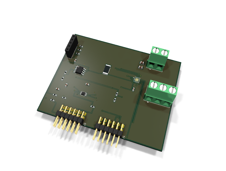
Catalog #7 in the AruviX actuator line, level L5 — the line's flagship, and a dual-PMOD module like the camera (axs-050). STSPIN230 (ST): 3-phase driver for 1.8–10 V, 1.3 A rms gimbal/ drone-class small motors.
Circuit review & bench-test guide →
Components#
Every placed component, with the reason it is on the board. Extracted directly from the schematic, so this cannot drift from the design.
| Ref | Value | What it does on this board | Part number | Footprint |
|---|---|---|---|---|
C1 |
10uF 25V X5R | VM bulk reservoir | GRM21BR61E106KA73LMurata |
C_0805_2012Metric |
C2 |
10uF 25V X5R | VM bulk reservoir | GRM21BR61E106KA73LMurata |
C_0805_2012Metric |
C3 |
100nF 16V X7R | VM high-frequency decoupling at the driver | GRM188R71C104KA01DMurata |
C_0603_1608Metric |
C4 |
100nF 16V X7R | INA240 supply decoupling | GRM188R71C104KA01DMurata |
C_0603_1608Metric |
C5 |
100nF 16V X7R | ADS7042 AVDD/DVDD decoupling | GRM188R71C104KA01DMurata |
C_0603_1608Metric |
C6 |
100nF 16V X7R | Mid-rail reference filter | GRM188R71C104KA01DMurata |
C_0603_1608Metric |
C7 |
1uF 10V X7R | Analog 3V3 bulk for the sense chain | GRM188R71A105KA61DMurata |
C_0603_1608Metric |
J1 |
PMOD A: DRIVE | PMOD peripheral plug (Digilent spec 1.2) | not selected generic |
PinHeader_2x06_P2.54mm_Horizontal |
J2 |
VM IN 1.8-10V | Motor supply input: 1 VM (1.8-10 V), 2 GND (joins PMOD GND here) | not selected Phoenix Contact |
TerminalBlock_Phoenix_MKDS-1,5-2-5.08_1x02_P5.08mm_Horizontal |
J3 |
PMOD B: SENSE | PMOD peripheral plug (Digilent spec 1.2) | not selected generic |
PinHeader_2x06_P2.54mm_Horizontal |
J4 |
PHASES (U/V/W) | Motor phases: 1 OUTU, 2 OUTV, 3 OUTW | not selected Phoenix Contact |
TerminalBlock_Phoenix_MKDS-1,5-3-5.08_1x03_P5.08mm_Horizontal |
J5 |
HALLS (3V3/GND/H1/H2/H3) | Hall sensor socket: 1 3V3, 2 GND, 3 H1, 4 H2, 5 H3 (open-collector OK) | not selected generic |
PinSocket_1x05_P2.54mm_Vertical |
R1 |
10k | EN/nFAULT open-drain pull-up (bidirectional enable/fault line) | RC0603FR-0710KLYageo Datasheet ↗ |
R_0603_1608Metric |
R2 |
100R | Series protection on the driver-driven nFAULT direction of EN | RC0603FR-07100RLYageo Datasheet ↗ |
R_0603_1608Metric |
R3 |
10k | STBY pull-down: power stage in standby until the host enables | RC0603FR-0710KLYageo Datasheet ↗ |
R_0603_1608Metric |
R4 |
10k | H1 pull-up (hall outputs are open-collector) | RC0603FR-0710KLYageo Datasheet ↗ |
R_0603_1608Metric |
R5 |
10k | H2 pull-up (hall outputs are open-collector) | RC0603FR-0710KLYageo Datasheet ↗ |
R_0603_1608Metric |
R6 |
10k | H3 pull-up (hall outputs are open-collector) | RC0603FR-0710KLYageo Datasheet ↗ |
R_0603_1608Metric |
R7 |
100R | Series protection on the hall-driven HALL1 line | RC0603FR-07100RLYageo Datasheet ↗ |
R_0603_1608Metric |
R8 |
100R | Series protection on the hall-driven HALL2 line | RC0603FR-07100RLYageo Datasheet ↗ |
R_0603_1608Metric |
R9 |
100R | Series protection on the hall-driven HALL3 line | RC0603FR-07100RLYageo Datasheet ↗ |
R_0603_1608Metric |
R10 |
0.05R 1% 2512 | Low-side shunt in the SENSEU/SENSEVW return (50 mV/A into the INA240) | not selected Vishay Datasheet ↗ |
R_2512_6332Metric |
R11 |
10k | INA240 REF divider top: mid-rail for bidirectional sensing | RC0603FR-0710KLYageo Datasheet ↗ |
R_0603_1608Metric |
R12 |
10k | INA240 REF divider bottom (zero current reads 3V3/2 = 0x800 ish) | RC0603FR-0710KLYageo Datasheet ↗ |
R_0603_1608Metric |
R13 |
100R | Series protection on the ADC-driven MISO line | RC0603FR-07100RLYageo Datasheet ↗ |
R_0603_1608Metric |
U1 |
STSPIN230 | Low-voltage 3-phase motor driver, 1.8-10 V, 1.3 A rms, integrated interlock | STSPIN230STMicroelectronics Datasheet ↗ |
VQFN-16-1EP_3x3mm_P0.5mm_EP1.8x1.8mm |
U2 |
INA240A1 | Bidirectional current-sense amp, 20 V/V, enhanced PWM rejection | INA240A1DTexas Instruments Datasheet ↗ |
SOIC-8_3.9x4.9mm_P1.27mm |
U3 |
ADS7042 | 12-bit 1 MSPS SPI SAR ADC, single-ended | ADS7042IDCURTexas Instruments Datasheet ↗ |
VSSOP-8_2.3x2mm_P0.5mm |
Signals#
Net labels used in the schematic, which are also the names the HDL top level should use.
3V3 ADC_SDO CS_N EN EN_FLT GND H1_RAW H2_RAW H3_RAW HALL1 HALL2 HALL3 INA_OUT INUH INUL INVH INVL INWH INWL MISO OUTU OUTV OUTW SCK SNS_P STBY VMOT VREF_MID
Production status#
| Schematic ERC | 0 violations |
|---|---|
| PCB layout | complete |
| DRC | 0 violations |
| Fab package | exported (24 gerbers + drill + CPL + BOM) |
| Fabricated | no — design stage only |
Source: boards/actuator-modules/axa-007-bldc
Catalog #7 in the AruviX actuator line (../README.md), level L5 — the line's flagship, and a dual-PMOD module like the camera (axs-050). STSPIN230 (ST): 3-phase driver for 1.8–10 V, 1.3 A rms gimbal/ drone-class small motors.
Status: schematic generated, ERC clean (0/0), netlist reviewed. PCB layout not started. Not released.
What it teaches (the FOC ladder)#
- Six-step hall commutation — read HALL1–3, table-commutate, spin.
- Hall-FOC — Clarke/Park transforms, PI current loop closed through the shunt→INA240→ADS7042 chain at PWM rate, SVPWM back out. Hardware FOC at 20 kHz+ loop rate is the actuator-side FPGA-beats-MCU demo.
- Sensorless — replace the halls with a back-EMF observer (later; the hall socket stays as the truth reference while you bring it up).
Design#
Drive (J1, PMOD A)#
- The STSPIN230 exposes SIX gate inputs (INxH/INxL per half-bridge), not the catalog sketch's "IN1–3" — documented deviation. The datasheet provides interlock protection, but commutation and dead time are still the fabric's job. J1 pins 1–3 = INUH/INVH/INWH, pins 7–9 = INUL/INVL/INWL.
- EN/nFAULT (J1 pin 4) is open-drain and bidirectional: 10 k pull-up on-module, 100 Ω series (line rule — it is driver-driven in the fault direction). The driver pulls it low on overcurrent/thermal fault; the host can also drive it low to kill the bridge. The fabric must watch it.
- STBY (J1 pin 10): STSPIN230 standby is entered with STBY low, so the 10 k pull-down keeps the power stage asleep until the host enables it — consistent with the line's default-off convention.
- Motor power VM 1.8–10 V on J2 screw terminal only; 2× 10 µF + 100 nF bulk. Phases OUTU/V/W on the J4 1x03 screw terminal. Grounds join here.
- Flyback: integrated bridge body diodes (line rule satisfied internally).
Sense (J3, PMOD B — Type 2 SPI positions + halls)#
- Single low-side shunt R10 = 0.05 Ω 1% 2512 in the SENSEU/SENSEVW return (both sense pins tie to the shunt top: one combined bus-current measurement; per-phase reconstruction from the active SVPWM vector is part of the L5 lesson).
- INA240A1 (20 V/V, enhanced PWM rejection — that feature is why this part: it holds its output flat while the bridge slews). REF1+REF2 tie to a 10k/10k mid-rail (1.65 V) so the output is bidirectional: zero current reads mid-scale, regen/decel reads below it. Chain gain: 50 mV/A × 20 = 1 V/A about 1.65 V.
- ADS7042 12-bit 1 MSPS SPI ADC (≈1.24 mA/LSB at 3.3 V full scale). Sample synchronous to the PWM valley — the fabric owns that timing, which is exactly why there is no MCU in this loop.
- Halls: 1x05 socket (3V3/GND/H1/H2/H3), 10 k pull-ups (open-collector halls) + 100 Ω series into J3 pins 7–9.
| J1 pin | 1 | 2 | 3 | 4 | 5 | 6 | 7 | 8 | 9 | 10 | 11 | 12 |
|---|---|---|---|---|---|---|---|---|---|---|---|---|
| Net | INUH | INVH | INWH | EN/nFAULT | GND | 3V3 | INUL | INVL | INWL | STBY | GND | 3V3 |
| J3 pin | 1 | 2 | 3 | 4 | 5 | 6 | 7 | 8 | 9 | 10 | 11 | 12 |
|---|---|---|---|---|---|---|---|---|---|---|---|---|
| Net | ~CS | NC | MISO | SCK | GND | 3V3 | HALL1 | HALL2 | HALL3 | NC | GND | 3V3 |
Deviation note: the task sketch placed the halls on PMOD A; they moved to PMOD B so all six timing-critical gate lines share one connector, and STBY took J1 pin 10 (the STSPIN230's six-input reality needs the pins).
Regenerate#
python3 generate_design.pyRemaining for release#
- [ ] PCB layout (dual plugs on 0.9" centers per PMOD spec 1.2.0, Kelvin shunt routing), DRC, fab outputs
- [ ]
hdl/: hall commutator → FOC core (Clarke/Park, PI, SVPWM) + ADS7042 SPI master, golden-model testbenches, ECP5 demo - [ ] Pin shunt MPN, BOM export and availability check, design-review checklist