Power boards
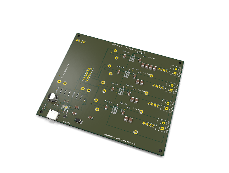
USB-C multi-rail power module
Circuit review & bench-test guide →
Components#
Every placed component, with the reason it is on the board. Extracted directly from the schematic, so this cannot drift from the design.
| Ref | Value | What it does on this board | Part number | Footprint |
|---|---|---|---|---|
C1 |
4.7uF 25V X7R | — | GRM31CR71H475KA12LMurata |
C_1206_3216Metric |
C2 |
330pF 50V C0G | — | GRM1885C1H331JA01DMurata |
C_0603_1608Metric |
C3 |
330pF 50V C0G | — | GRM1885C1H331JA01DMurata |
C_0603_1608Metric |
C5 |
10uF 25V X7R | — | GRM31CR71E106KA12LMurata |
C_1206_3216Metric |
C6 |
10uF 25V X7R | — | GRM31CR71E106KA12LMurata |
C_1206_3216Metric |
C7 |
47uF 25V POLYMER | — | 25SVPF47MPanasonic |
CP_Elec_6.3x5.9 |
C9 |
4.7nF 50V C0G | — | GRM1885C1H472JA01DMurata |
C_0603_1608Metric |
C10 |
4.7uF 50V X7R | — | GRM31CR71H475KA12LMurata |
C_1206_3216Metric |
C11 |
4.7uF 50V X7R | — | GRM31CR71H475KA12LMurata |
C_1206_3216Metric |
C12 |
1uF 6.3V X7R | — | GRM188R71C105KA12DMurata |
C_0603_1608Metric |
C13 |
100uF 6.3V X5R | — | GRM32ER60J107ME20LMurata |
C_1210_3225Metric |
C14 |
100uF 6.3V X5R | — | GRM32ER60J107ME20LMurata |
C_1210_3225Metric |
C15 |
100uF 6.3V X5R | — | GRM32ER60J107ME20LMurata |
C_1210_3225Metric |
C16 |
100uF 6.3V X5R | — | GRM32ER60J107ME20LMurata |
C_1210_3225Metric |
C17 |
4.7uF 50V X7R | — | GRM31CR71H475KA12LMurata |
C_1206_3216Metric |
C18 |
4.7uF 50V X7R | — | GRM31CR71H475KA12LMurata |
C_1206_3216Metric |
C19 |
1uF 6.3V X7R | — | GRM188R71C105KA12DMurata |
C_0603_1608Metric |
C20 |
100uF 6.3V X5R | — | GRM32ER60J107ME20LMurata |
C_1210_3225Metric |
C21 |
100uF 6.3V X5R | — | GRM32ER60J107ME20LMurata |
C_1210_3225Metric |
C22 |
4.7uF 50V X7R | — | GRM31CR71H475KA12LMurata |
C_1206_3216Metric |
C23 |
4.7uF 50V X7R | — | GRM31CR71H475KA12LMurata |
C_1206_3216Metric |
C24 |
1uF 6.3V X7R | — | GRM188R71C105KA12DMurata |
C_0603_1608Metric |
C25 |
47uF 10V X7R | — | GRM32ER71A476ME15LMurata |
C_1210_3225Metric |
C26 |
47uF 10V X7R | — | GRM32ER71A476ME15LMurata |
C_1210_3225Metric |
C27 |
4.7uF 50V X7R | — | GRM31CR71H475KA12LMurata |
C_1206_3216Metric |
C28 |
4.7uF 50V X7R | — | GRM31CR71H475KA12LMurata |
C_1206_3216Metric |
C29 |
1uF 6.3V X7R | — | GRM188R71C105KA12DMurata |
C_0603_1608Metric |
C30 |
47uF 10V X7R | — | GRM32ER71A476ME15LMurata |
C_1210_3225Metric |
C31 |
47uF 10V X7R | — | GRM32ER71A476ME15LMurata |
C_1210_3225Metric |
C32 |
10nF 25V X7R | — | GRM188R71H103KA01DMurata |
C_0603_1608Metric |
C33 |
10nF 25V X7R | — | GRM188R71H103KA01DMurata |
C_0603_1608Metric |
C34 |
10nF 25V X7R | — | GRM188R71H103KA01DMurata |
C_0603_1608Metric |
C35 |
10nF 25V X7R | — | GRM188R71H103KA01DMurata |
C_0603_1608Metric |
D1 |
TVS2200 | 22 V flat-clamp VBUS surge and IEC ESD protector | TVS2200DRVRTexas Instruments Datasheet ↗ |
WSON-6-1EP_2x2mm_P0.65mm_EP1x1.6mm |
D2 |
SS34 | Negative VBUS surge clamp | SS34-E3/57TVishay Datasheet ↗ |
D_SMA |
J1 |
USB4105-GF-A-120 | USB Type-C power-only receptacle | USB4105-GF-A-120GCT Datasheet ↗ |
USB_C_Receptacle_GCT_USB4105-xx-A_16P_TopMnt_Horizontal |
J2 |
CONTROL / SEQUENCING DNP | Optional control header | — | PinHeader_2x06_P2.54mm_Vertical |
J3 |
PD DIAGNOSTIC I2C DNP | Optional PD diagnostic header | — | PinHeader_1x04_P2.54mm_Vertical |
J4 |
1V1 POWER OUT DNP | Optional 5.08 mm full-load terminal | 1715721 |
TerminalBlock_Phoenix_MKDS-1,5-2-5.08_1x02_P5.08mm_Horizontal |
J5 |
1V1 BREADBOARD LIGHT LOAD DNP | Optional duplicated light-load header | — | PinHeader_1x04_P2.54mm_Vertical |
J6 |
1V8 POWER OUT DNP | Optional 5.08 mm full-load terminal | 1715721 |
TerminalBlock_Phoenix_MKDS-1,5-2-5.08_1x02_P5.08mm_Horizontal |
J7 |
1V8 BREADBOARD LIGHT LOAD DNP | Optional duplicated light-load header | — | PinHeader_1x04_P2.54mm_Vertical |
J8 |
3V3 POWER OUT DNP | Optional 5.08 mm full-load terminal | 1715721 |
TerminalBlock_Phoenix_MKDS-1,5-2-5.08_1x02_P5.08mm_Horizontal |
J9 |
3V3 BREADBOARD LIGHT LOAD DNP | Optional duplicated light-load header | — | PinHeader_1x04_P2.54mm_Vertical |
J10 |
5V0 POWER OUT DNP | Optional 5.08 mm full-load terminal | 1715721 |
TerminalBlock_Phoenix_MKDS-1,5-2-5.08_1x02_P5.08mm_Horizontal |
J11 |
5V0 BREADBOARD LIGHT LOAD DNP | Optional duplicated light-load header | — | PinHeader_1x04_P2.54mm_Vertical |
R1 |
162k 1% | — | RC0603FR-07162KLYageo Datasheet ↗ |
R_0603_1608Metric |
R2 |
38.3k 1% | — | RC0603FR-0738K3LYageo Datasheet ↗ |
R_0603_1608Metric |
R3 |
140k 1% | — | RC0603FR-07140KLYageo Datasheet ↗ |
R_0603_1608Metric |
R4 |
60.4k 1% | — | RC0603FR-0760K4LYageo Datasheet ↗ |
R_0603_1608Metric |
R5 |
162k 1% | — | RC0603FR-07162KLYageo Datasheet ↗ |
R_0603_1608Metric |
R6 |
38.3k 1% | — | RC0603FR-0738K3LYageo Datasheet ↗ |
R_0603_1608Metric |
R7 |
191k 1% | — | RC0603FR-07191KLYageo Datasheet ↗ |
R_0603_1608Metric |
R8 |
9.53k 1% | — | RC0603FR-079K53LYageo Datasheet ↗ |
R_0603_1608Metric |
R9 |
10k 1% | — | RC0603FR-0710KLYageo Datasheet ↗ |
R_0603_1608Metric |
R10 |
10k 1% | — | RC0603FR-0710KLYageo Datasheet ↗ |
R_0603_1608Metric |
R11 |
3.3k | — | RC0603FR-073K3LYageo Datasheet ↗ |
R_0603_1608Metric |
R12 |
3.3k | — | RC0603FR-073K3LYageo Datasheet ↗ |
R_0603_1608Metric |
R13 |
10k | — | RC0603FR-0710KLYageo Datasheet ↗ |
R_0603_1608Metric |
R14 |
1M | — | RC0603FR-071MLYageo Datasheet ↗ |
R_0603_1608Metric |
R15 |
33.2k 1% | — | RC0603FR-0733K2LYageo Datasheet ↗ |
R_0603_1608Metric |
R16 |
100k | — | RC0603FR-07100KLYageo Datasheet ↗ |
R_0603_1608Metric |
R17 |
47k | — | RC0603FR-0747KLYageo Datasheet ↗ |
R_0603_1608Metric |
R18 |
1.00k 1% | — | RC0603FR-071KLYageo Datasheet ↗ |
R_0603_1608Metric |
R19 |
10.0k 1% | — | RC0603FR-0710KLYageo Datasheet ↗ |
R_0603_1608Metric |
R20 |
0R BOOT | — | RC0603JR-070RLYageo Datasheet ↗ |
R_0603_1608Metric |
R21 |
22.1k 1% | — | RC0603FR-0722K1LYageo Datasheet ↗ |
R_0603_1608Metric |
R22 |
100k | — | RC0603FR-07100KLYageo Datasheet ↗ |
R_0603_1608Metric |
R23 |
47k | — | RC0603FR-0747KLYageo Datasheet ↗ |
R_0603_1608Metric |
R24 |
8.06k 1% | — | RC0603FR-078K06LYageo Datasheet ↗ |
R_0603_1608Metric |
R25 |
10.0k 1% | — | RC0603FR-0710KLYageo Datasheet ↗ |
R_0603_1608Metric |
R26 |
0R BOOT | — | RC0603JR-070RLYageo Datasheet ↗ |
R_0603_1608Metric |
R27 |
16.5k 1% | — | RC0603FR-0716K5LYageo Datasheet ↗ |
R_0603_1608Metric |
R28 |
100k | — | RC0603FR-07100KLYageo Datasheet ↗ |
R_0603_1608Metric |
R29 |
47k | — | RC0603FR-0747KLYageo Datasheet ↗ |
R_0603_1608Metric |
R30 |
23.2k 1% | — | RC0603FR-0723K2LYageo Datasheet ↗ |
R_0603_1608Metric |
R31 |
10.0k 1% | — | RC0603FR-0710KLYageo Datasheet ↗ |
R_0603_1608Metric |
R32 |
0R BOOT | — | RC0603JR-070RLYageo Datasheet ↗ |
R_0603_1608Metric |
R33 |
13.0k 1% | — | RC0603FR-0713KLYageo Datasheet ↗ |
R_0603_1608Metric |
R34 |
100k | — | RC0603FR-07100KLYageo Datasheet ↗ |
R_0603_1608Metric |
R35 |
47k | — | RC0603FR-0747KLYageo Datasheet ↗ |
R_0603_1608Metric |
R36 |
40.2k 1% | — | RC0603FR-0740K2LYageo Datasheet ↗ |
R_0603_1608Metric |
R37 |
10.0k 1% | — | RC0603FR-0710KLYageo Datasheet ↗ |
R_0603_1608Metric |
R38 |
0R BOOT | — | RC0603JR-070RLYageo Datasheet ↗ |
R_0603_1608Metric |
R39 |
47k | — | RC0603FR-0747KLYageo Datasheet ↗ |
R_0603_1608Metric |
R40 |
47k | — | RC0603FR-0747KLYageo Datasheet ↗ |
R_0603_1608Metric |
TP1 |
VBUS_RAW | Electrical test point | — | TestPoint_Plated_Hole_D2.0mm |
TP2 |
PD_15V | Electrical test point | — | TestPoint_Plated_Hole_D2.0mm |
TP3 |
CC1 | Electrical test point | — | CC_TestPoint_D0.6mm |
TP4 |
CC2 | Electrical test point | — | CC_TestPoint_D0.6mm |
TP5 |
GND | Electrical test point | — | TestPoint_Plated_Hole_D2.0mm |
TP6 |
VOUT_1V1 | Electrical test point | — | TestPoint_Plated_Hole_D2.0mm |
TP7 |
VOUT_1V8 | Electrical test point | — | TestPoint_Plated_Hole_D2.0mm |
TP8 |
VOUT_3V3 | Electrical test point | — | TestPoint_Plated_Hole_D2.0mm |
TP9 |
VOUT_5V0 | Electrical test point | — | TestPoint_Plated_Hole_D2.0mm |
TP10 |
EN_1V1 | Electrical test point | — | TestPoint_Plated_Hole_D2.0mm |
TP11 |
PG_1V1 | Electrical test point | — | TestPoint_Plated_Hole_D2.0mm |
TP12 |
EN_1V8 | Electrical test point | — | TestPoint_Plated_Hole_D2.0mm |
TP13 |
PG_1V8 | Electrical test point | — | TestPoint_Plated_Hole_D2.0mm |
TP14 |
EN_3V3 | Electrical test point | — | TestPoint_Plated_Hole_D2.0mm |
TP15 |
PG_3V3 | Electrical test point | — | TestPoint_Plated_Hole_D2.0mm |
TP16 |
EN_5V0 | Electrical test point | — | TestPoint_Plated_Hole_D2.0mm |
TP17 |
PG_5V0 | Electrical test point | — | TestPoint_Plated_Hole_D2.0mm |
TP18 |
PD_SINK_EN_N | Electrical test point | — | TestPoint_Plated_Hole_D2.0mm |
U1 |
TPS25730AD | PD3.2 sink controller with integrated protected 5 A path | TPS25730ADREFRTexas Instruments Datasheet ↗ |
Texas_REF0038A_WQFN-38-2EP_6x4mm_P0.4 |
U2 |
TPSM63603 | 36 V input 3 A integrated-inductor synchronous buck module | TPSM63603RDHRTexas Instruments Datasheet ↗ |
Texas_RDH0030A_B0QFN-30_4x6mm |
U3 |
TPSM63603 | 36 V input 3 A integrated-inductor synchronous buck module | TPSM63603RDHRTexas Instruments Datasheet ↗ |
Texas_RDH0030A_B0QFN-30_4x6mm |
U4 |
TPSM63603 | 36 V input 3 A integrated-inductor synchronous buck module | TPSM63603RDHRTexas Instruments Datasheet ↗ |
Texas_RDH0030A_B0QFN-30_4x6mm |
U5 |
TPSM63603 | 36 V input 3 A integrated-inductor synchronous buck module | TPSM63603RDHRTexas Instruments Datasheet ↗ |
Texas_RDH0030A_B0QFN-30_4x6mm |
Signals#
Net labels used in the schematic, which are also the names the HDL top level should use.
ADCIN1 ADCIN2 ADCIN3 ADCIN4 CAP_MIS_N CBOOT_1V1 CBOOT_1V8 CBOOT_3V3 CBOOT_5V0 CC1 CC2 EN_1V1 EN_1V8 EN_3V3 EN_5V0 FB_1V1 FB_1V8 FB_3V3 FB_5V0 GND PD5VMAX PD_15V PD_FAULT_N PD_I2C_SCL PD_I2C_SDA PD_LDO_1V5 PD_LDO_3V3 PD_RESERVED26 PD_SINK_EN_N PG_1V1 PG_1V8 PG_3V3 PG_5V0 RBOOT_1V1 RBOOT_1V8 RBOOT_3V3 RBOOT_5V0 RT_1V1 RT_1V8 RT_3V3 RT_5V0 USB_SHIELD VBUS_RAW VCC_1V1 VCC_1V8 VCC_3V3 VCC_5V0 VOUT_1V1 VOUT_1V8 VOUT_3V3 VOUT_5V0
Production status#
| Schematic ERC | not run |
|---|---|
| PCB layout | complete |
| DRC | not run |
| Fab package | not exported |
| Fabricated | no — design stage only |
Source: boards/usb-c-multi-rail-power
Status#
Rev 0.1 schematic capture and four-layer PCB routing are complete. KiCad 10.0.4 reports 0 ERC violations, 0 DRC violations, 0 unconnected items, and 0 schematic/PCB parity issues. The 115 mm x 95 mm board has 113 footprints, 67 nets, 540 routed segments, 195 vias, and 14 zones.
The automated preflight reports 28 PASS, 5 CONDITIONAL, 7 OPEN, and 0 FAIL. Gerbers, separate PTH/NPTH drills, a qualified 81-line core-SMT BOM, pick-and-place data, checksums, fabrication ZIP, and visual-review outputs are under manufacturing/. See the detailed qa/report.html.
This is an engineering prototype release, not a production release or regulatory certification. Exact capacitor curves and physical bench/compliance gates remain open.
Purpose#
This board converts a USB-C Power Delivery input into four simultaneous, independently controlled hobby/FPGA supply rails:
| Rail | Rated output | Primary use |
|---|---|---|
| 1.1 V | 3 A | FPGA/ASIC core experiments |
| 1.8 V | 3 A | auxiliary and low-voltage I/O |
| 3.3 V | 3 A | digital I/O and peripherals |
| 5.0 V | 3 A | modules, sensors, and downstream conversion |
The 3 A rating is per channel. The normal input contract is 15 V at 3 A (45 W), which supports all four rails at their full 33.6 W combined output only when conversion, connector, and thermal losses remain inside the verified budget.
Frozen rev-0.1 architecture#
USB-C receptacle
    -> TVS2200 positive-surge clamp + SS34 negative-transient clamp
    -> TPS25730AD protected PD3.2 sink path
       (hardware-strapped for exactly 15 V / 3 A;
        sink path disabled on capability mismatch)
    -> PD_15V protected intermediate bus
       |-> TPSM63603 -> 1.1 V / 3 A
       |-> TPSM63603 -> 1.8 V / 3 A
       |-> TPSM63603 -> 3.3 V / 3 A
`-> TPSM63603 -> 5.0 V / 3 A- The TPS25730ADREFR includes the high-voltage sink switch, reverse-current protection, overvoltage supervision, and resistor-strapped PD policy. It does not require an MCU, EEPROM, or production firmware image.
- Each TPSM63603RDHR contains its inductor and power switches, accepts up to 36 V during normal operation, and exposes enable and power-good signals.
- A charger that cannot provide a 15 V / 3 A contract must not power the converter tree. There is deliberately no reduced-power 5 V fallback.
- All four rails default to enabled after a valid PD contract. Each rail enable and power-good signal is exposed for external sequencing.
- A 47 uF / 25 V polymer capacitor plus the eight converter-input MLCCs form the protected-bus bank. Worst positive tolerance is 97.76 uF, below the 100 uF limit; exact MLCC DC-bias curves remain an AVL evidence gate.
Interfaces#
- One 5.08 mm two-pin terminal block per output for full-load wiring.
- One duplicate 2.54 mm four-pin header per output (two rail pins and two GND pins) for light-load breadboard work only.
- A 2x6 control header exposes each rail enable and power-good signal, the PD capability-mismatch output, master fault input, 3.3 V logic reference, and GND.
- A separate four-pin diagnostic header exposes the PD controller I2C target interface. I2C is optional and is not required for normal operation.
- Test points cover raw VBUS, protected 15 V, all outputs, CC1/CC2, control signals, and GND.
J2-J11 are DNP in the core single-sided SMT build. The control/diagnostic headers, terminal blocks, and breadboard headers therefore require a secondary through-hole assembly operation. Qualify SMT connector alternatives if the final product must have zero manual assembly.
Do not route 2-3 A through a solderless breadboard or Dupont jumper. Use the terminal blocks and appropriately sized wire for load and thermal testing.
Design authorities#
- TI TPS25730A data sheet
- TI TPSM63603 data sheet
- TI TVS2200 data sheet
- GCT USB4105 mechanical drawing
- GCT USB4105 product specification
- Panasonic 25SVPF47M OS-CON series
Release gates#
- [x] Freeze 15 V / 3 A input contract and four 3 A output targets.
- [x] Select a firmware-free PD3.2 controller with protected sink path.
- [x] Select a 36 V-tolerant integrated-inductor regulator family.
- [x] Calculate feedback, frequency, minimum effective capacitance, and input power budget.
- [x] Complete schematic capture and pass ERC with zero errors and warnings.
- [x] Independently verify the custom TPSM63603 RDH0030A land pattern against the TI package drawing.
- [x] Complete four-layer placement/routing and pass DRC, connectivity, and schematic-parity checks.
- [x] Analytically validate strap corners, feedback values, capacitance windows, power budget, copper drop, and preliminary thermal behavior.
- [x] Run averaged ngspice protected-bus startup, combined-load, and source-mismatch scenarios.
- [ ] Archive exact vendor DC-bias curves for the production capacitor lots; the 1.1 V and 1.8 V output banks have the narrowest worst-corner margin.
- [ ] Assemble prototypes and complete the documented bench matrix.
- [x] Generate and inspect Gerbers, drills, BOM, pick-and-place, schematic PDF, assembly PDF, SVG preview, checksums, and fabrication ZIP.
- [ ] Complete USB-IF/EMC/safety/environmental work required for any external certification claim.
Local commands#
# Schematic and local libraries
python3 boards/usb-c-multi-rail-power/generate_design.py

# PCB: use KiCad's bundled Python so pcbnew matches KiCad
/Applications/KiCad/KiCad.app/Contents/Frameworks/Python.framework/Versions/Current/bin/python3 \
  boards/usb-c-multi-rail-power/generate_pcb.py

# Fabrication/assembly package, then full QA + HTML report
python3 boards/usb-c-multi-rail-power/manufacturing/generate_outputs.py
python3 boards/usb-c-multi-rail-power/qa/run_preflight.py
The PCB generator refuses to overwrite the production file while a KiCad project lock exists. Close the board before intentionally regenerating it; do not use --force over an active editor session.